Commputer Assembly
One of the basic skills that you must acquire in computer system servicing is to independently assemble a personal computer or simply setting up a PC. After familiarizing with all the tools, devices, peripherals and safety precautions I believe that you are now ready to gain another experience in CCS by going through this lesson.

Step 1. Prepare your workplace
1. Take Inventory:
Before you start, take an inventory of your parts. Do not begin assembling your computer if you don’t have everything you need. Begin the step-by-step process once you are ready with everything you need.
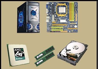
Figure 1. Take inventory of the Different Computer Parts
2. Make Space, Make Time:
Building a PC takes up space – about a dining room table worth. So make sure you have plenty of working room and a few hours to proceed with minimal interruption. Work on a flat, stable table top surface, or bare floor, where you have room to layout all of the items.
3. Prepare Grounding Protection:
Use an inexpensive antistatic wrist strap. Make sure you are wearing your antistatic wrist strap correctly (it does you no good at all if you do not wear it!), and you are ready to proceed. Look at Figure 2 for details.
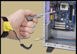
Figure 2. Wearing the Anti- static Wrist Strap Correctly
4. Have the Drivers Ready:
Assuming you have another internet connected PC, download the latest drivers from the vendors’ websites for each component you will be installing. Sometimes drivers are updated between the time the component was manufactured and the time you are installing it. It is always best to have the latest. Copy them to a CD for easy access.
Step 2. Prepare the Motherboard
1. Great care should be taken when installing the motherboard. First, take the board out of its packaging and put it on top of the antistatic bag it came in (see Figure 4). Remember, you always want to safeguard your components from potentially hazardous static electricity (wear your strap).
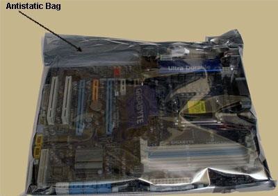
Figure 3. Motherboard in an Antistatic Bag
2. Before you secure the motherboard onto the PC case/chassis, inspect it carefully for any visible defects.
3. Next, review the motherboard manual, to make sure you are familiar with the motherboard layout and understand which socket is which. Manuals are extremely helpful, usually easy to read, and include illustrations. Below you can find instructions on how to install the processor, the heat sink and the memory modules on the motherboard. You should not place the motherboard in the computer case until you are told to do so.
Step 3. Install the CPU
1. Use the unlocking mechanism to open the CPU socket which is usually a lever.
2. Carefully line up the pins and place the chip in its socket; it will fit only when oriented the proper way. An arrow or a missing pin on one corner of the chip will show you how to line things up.
3. Align Triangular CPU and socket key marks as shown in Figure 4.
4. Lower the lever to lock the CPU into place.
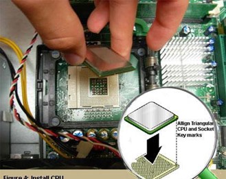
Figure 4. Install CPU

Step 4. Install the CPU Heat Sink
1. Follow the manufacturer’s directions to install the heat sink and the fan that will cool the processor. If you bought an OEM CPU and a separate heat sink, you may need to spread a thin layer of the thermal grease that came with the heat sink over the chip to ensure proper transfer of heat (some heat sinks come with this grease already applied).
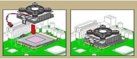
Figure 5. Install CPU Heat Sink
3. Attach the clip that holds the heat sink in place keeping in mind that it may require a fair amount of force. Again, follow the instructions that came with the heat sink. They will show you how to fit it correctly. If you are in doubt, you can visit the manufacturer’s website for more information.
4. Plug the CPU fan’s power connector into the proper connector on the motherboard.
Step 5. Install Memory (RAM Modules)
In order to install the memory modules, insert them into the proper sockets (Figure 6) and push down firmly but evenly until the clips on both sides of the socket pop into place. If your motherboard supports dual- channel memory, consult the user manual to determine which pairs of RAM sockets you should use. The motherboard and the CPU are the brain and nerve center of your PC, so selecting these components is the most important decision you’ll make.
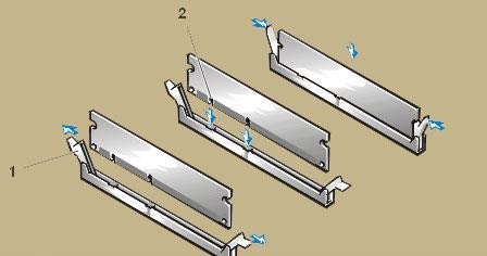
Figure 6. Install RAM Memory
Step 6. Place the motherboard into the case
1. Some PC cases have a removable motherboard tray. If yours does, remove the screws holding it in place and pull it out of the case (Figure 8).
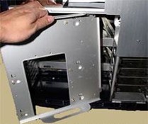
Figure 7. Remove Motherboard Tray
2. Note the pattern of the holes in your motherboard (Figure 9), and screw brass standoffs into the motherboard tray or into the PC case in the correct locations (ALWAYS check the manual and follow their instructions to the letter).
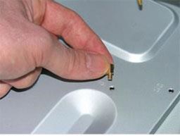
Figure 8. Screw Brass Standoffs into the Motherboard
3. Check the layout of the sockets on the motherboard, and confirm that the ports on your motherboard’s back panel match the holes on the case’s Input/Output (I/O) shield that is installed in your case. If necessary, remove the old I/O shield by tapping it firmly a few times with the butt-end of a screwdriver, and then replace it with the shield that came with the new motherboard.
4. Carefully position the motherboard on top of the brass standoffs (Figure 10), line up all the holes, and use the screws that accompanied the case to fasten down the motherboard. If you are using a removable tray in your system, slide the tray and motherboard back into the case and then secure the tray.
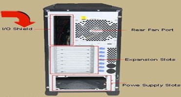
Figure 9. Case’s I /O Shield
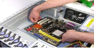
Figure 10. Mount the Motherboard
Step 7. Connect the Power Supply
Making the proper connections is crucial to successfully assembling your PC system. Fortunately, manufacturers provide color-coded power cables and unique connector shapes to make the job easy.
1. First, plug the large ATX power connector (Figure 12) from your power supply into the matching port on your motherboard. Look Figure X for details.
2. Locate the smaller, square processor power connector (Figure 13) (you cannot miss it – it is the one sprouting the yellow and black wires) and attach it to the motherboard. Note: your connector is usually located near the processor. As always, refer to your motherboard’s manual for the exact locations.
3. Use your motherboard user manual and find the description about front-panel connectors.
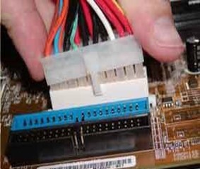
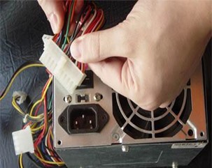
Figure 11. Connect the ATX Power in the Motherboard
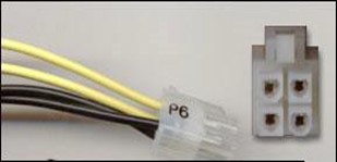
Figure 12. Square Processor Power Connector
NOTE:
You are going to be doing work that requires attention to detail and can be quite frustrating if you do not go into it with the right attitude.
4. Attach each of the tiny leads from the power and reset switches (Figure 15), the hard-disk activity lights, the PC speaker, and any front-panel USB and FireWire ports to the corresponding pin on your motherboard. The needle-nose pliers are useful for manipulating small pieces.
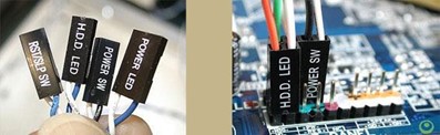
Figure 13. Connect the different Leads
Step 8. Install Graphics / Video Cards
1. Begin by removing the backplane cover from the AGP or PCI Express X16 slot (the metal piece where the monitor connector will emerge) (Figure 14).
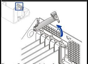
Figure 14. Remove the backplane cover
2. Install the graphics board in that slot, and then secure the card with a screw (Figure 15).
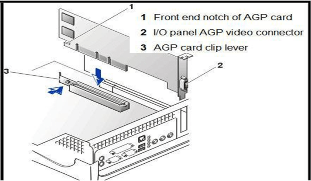
Figure 15. Install the Graphics Board

Step 9. Install Internal Drives
Now it is time to install your drives. This is an easy process, but it requires attention to detail.
1. Make any necessary changes to jumpers on the drives before mounting them in the case. A two-drive system (one or two SATA (Serial ATA- is a standard hardware interface for connecting hard drives and CD/DVD drives to a computer) hard drives, plus one parallel ATA (Advanced Technology Attachment) optical drive, for example) is easy to set up; the SATA drives are jumper less, and the optical drive can be set as master on its own parallel ATA channel. Many cases have removable drive rails or cages to house drives.
2. Use the included screws to attach your drives to the rails or cage, and slide them into the case. For externally accessible drives such as a DVD recorder, you can save time by installing one drive rail and sliding the drive in for a test fitting to make sure that its front is flush with the case (Figure 16).
3. When the drives are installed, connect power and data cables to each one. Parallel ATA drives use wide, flat data cables that can be installed only in the correct way. Floppy drives use a similar but smaller cable; SATA drives use a thin, 1cm-wide data cable. SATA drives use a new type of power connector that many power supplies don’t come with. Fortunately, many motherboards ship with adapters for converting a standard four-pin power connector to a SATA power connector (Figure 16).
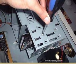
Figure 16. Attach your devices

Figure 17. Connect Power Connector

Step 10. Install the Add- in Cards
1. For each add-in card, you must choose a free PCI slot.
2. Remove its backplane cover to allow access from the rear of the case.
3. Carefully position the card above the slot, and press down firmly to seat the card (Figure 18).
4. Secure the card with a screw.
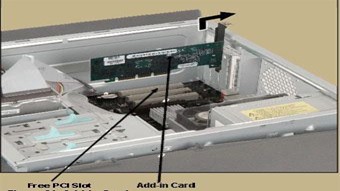
Figure 18. Add- in Cards
Many motherboards have additional sound connectors or ports housed on small add-in boards. Some of these plug into slots on the motherboard; others screw into the back of the case in place of slot covers. Usually the additional ports are not essential to your PC’s operation. For example, if you install a sound card, you do not need connectors to the motherboard’s built-in sound chip. Check your motherboard manual to determine what each of these boards does.
Connecting Peripherals of a Personal Computer
When attaching hardware and peripherals of the computer, ensure that they are connected to the correct locations or ports. For example, some mouse and keyboard cables use the same type of PS/2 connector. So, you must know first the different ports that can be found in the back panel of the computer.
Keep in mind:
- When attaching cables, never force a connection.
- Plug in the power cable after you have connected all other
Steps in Connecting Peripherals of a PC
Step 1. Attach the monitor cable to the video port.
Step 2. Secure the cable by tightening the screws on the connector.
Step 3. Plug the keyboard cable into the PS/2 keyboard port.
Step 4. Plug the mouse cable into the PS/2 mouse port.
Step 5. Plug the USB cable into a USB port.
Step 6. Plug the network cable into the network port.
Step 7. Plug the power cable into the power supply.

Figure 19. Steps in Connecting Peripherals of a PC
After connecting all the cables into their proper places, the picture in the next page should be the appearance of the back panel of your PC.
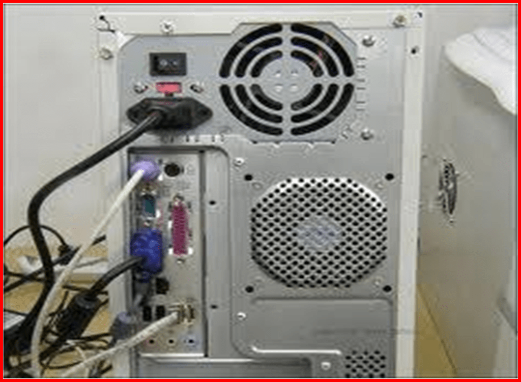
Figure 20. Appearance of the PC’s Back Panel


